8 875,00 zł (netto)
10 916,25 zł (brutto)
The calculations in the calculator are approximate. The bank will prepare a final offer for you once you submit your installment application.

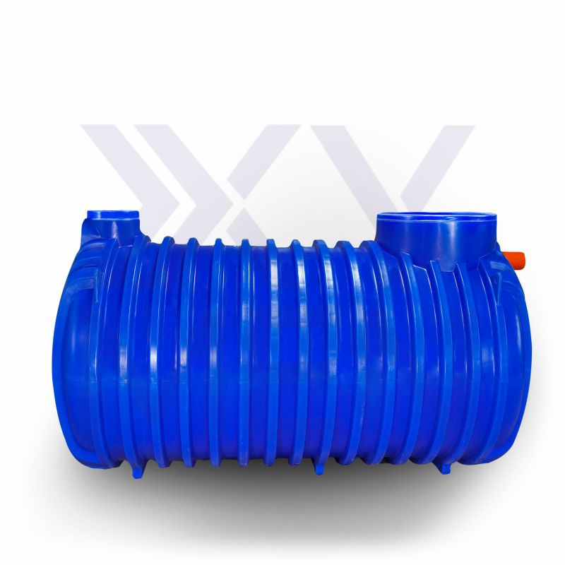
| Capacity | 4000 L |
| Number of users | 8 people |
| Length | 2900 mm |
| Width | 1400 mm |
| Height | 1600 mm |
| Height to inlet | 1370 mm |
| Height to outlet | 1310 mm |
| Inlet diameter | 160 mm |
| Outlet diameter | 110 mm |
| Large manhole diameter | 615 mm |
| Small manhole diameter | 245 mm |
| Tank weight | 170 kg |
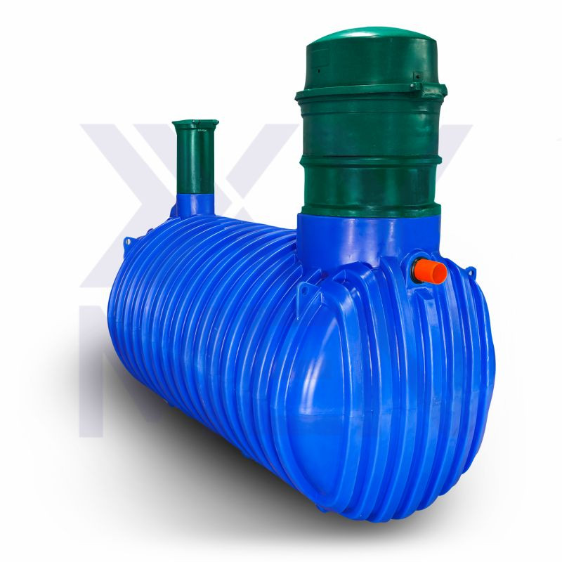
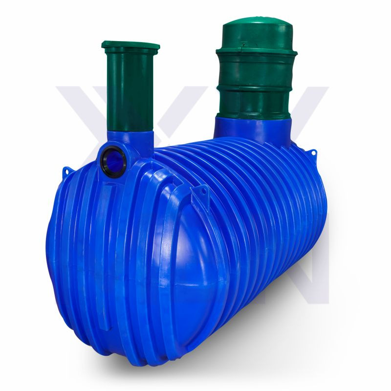
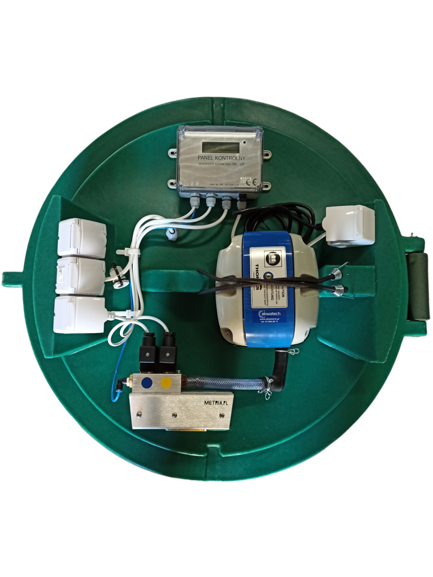
METRIA SOFT SBR 8 domestic wastewater treatment plant
This treatment plant operates using process-based wastewater treatment technology. The treatment process consists of several consecutive stages controlled by a computer system, which manages aeration, sedimentation and flotation, as well as pumping the wastewater using a macerator pump. The treated wastewater can then be safely discharged into the environment.
The tanks are manufactured from high-quality HDPE using the rotational molding (rotomolding) method. This plastic forming technique involves a mold, divided into two or more parts, being filled with plastic powder or granules, then placed in an oven where the material melts and, through the rotation of the mold, forms a monolithic tank. The tanks are produced in accordance with the PN-EN 12566-3+A2:2013 standard, ensuring high quality, watertightness, and durability.
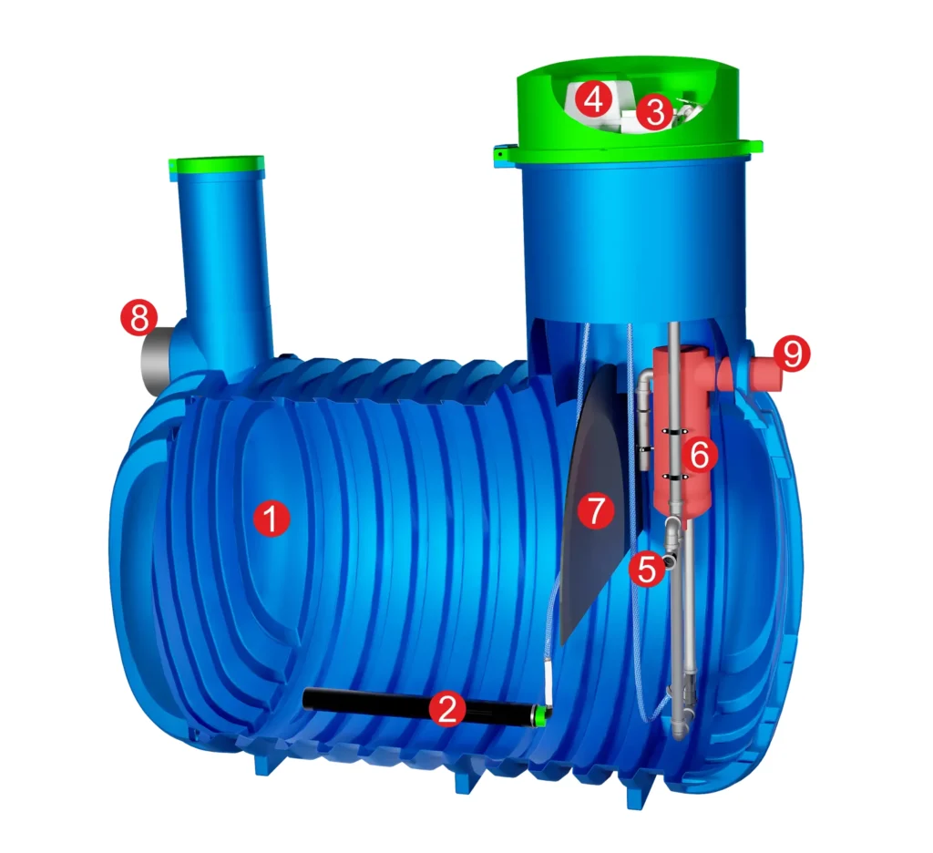
1. Treatment plant tank – biological reactor
2. Diffuser
3. Treatment plant controller
4. Aeration blower
5. Macerator pump
6. Clarification chamber – secondary sedimentation tank
7. Baffle
8. Wastewater inflow
9. Treated wastewater outflow
The SOFT SBR treatment plant combines two technologies: the simplicity of solutions used in conventional flow-through treatment plants and the sequential treatment system found in SBR plants. The SOFT SBR plant operates using Sequencing Batch Reactor (SBR) technology. The treatment process consists of several consecutive sequences controlled by a computer system, which manages aeration, sedimentation and flotation, as well as pumping the wastewater using a macerator pump. The SOFT SBR plant is designed for treating domestic wastewater. The treated wastewater can then be safely discharged into the environment.
Stage 1 – Wastewater is aerated using a diffuser, which forms activated sludge (bacteria aggregated in flocs) that mixes with subsequent portions of wastewater. Through this controlled aeration process, the wastewater undergoes biological treatment.
Stage 2 – The controller switches off aeration to allow the wastewater to settle. In the tank, a separation process occurs: contaminants lighter than water rise to the surface, while heavier particles settle at the bottom, forming a layer of sludge.
Stage 3 – In this stage, the pump discharges the treated wastewater from the tank into the infiltration system. The system is designed to avoid discharging substances from the surface or the bottom, allowing only the treated wastewater from the middle layer to be released.
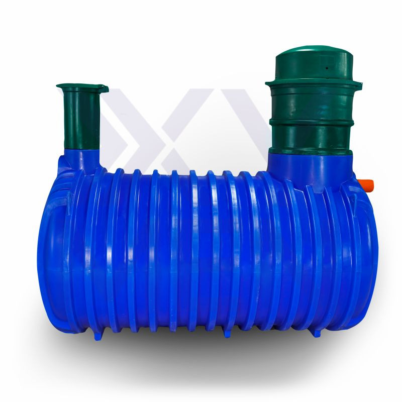
– heavily ribbed structure ensures resistance to soil pressure
– small dimensions
– even and stable wastewater treatment, resulting in higher reduction of contaminants in the wastewater
– no addition of bio-preparations required
– low electricity consumption
– installation possible in difficult soil conditions
– sludge removal once every 12–24 months
– does not emit unpleasant odors like a traditional cesspool
– 30-year warranty
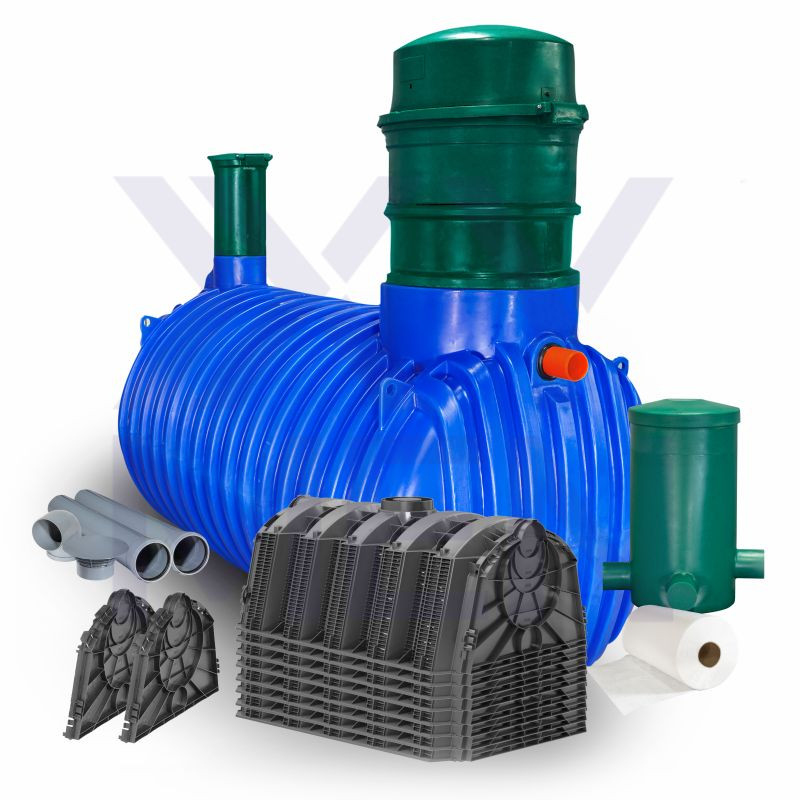
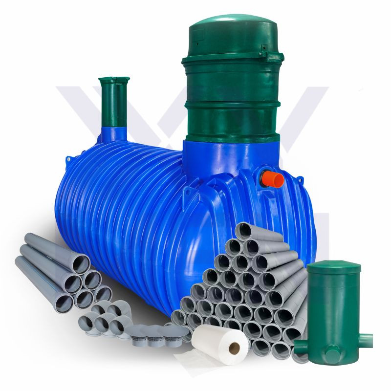
The treatment plant includes:
– Metria Soft SBR treatment plant tank,
– DN600 cover with controller,
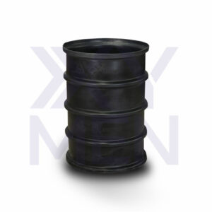
– DN600 extension riser, H-0.5 m.
Treatment plant with 72 m drainage system includes:
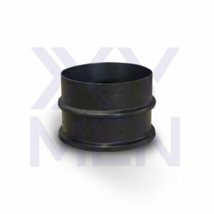
– PVC pipe DN 110 grey, 1 m – 6 pcs.
– Distribution manhole DN400 H-0.7 m or DN400 H-0.5 m or DN400 H-1.1 m – 1 pc.
– PVC elbow DN 110 87° grey – 5 pcs.
– PVC drainage pipes DN 110 grey, 2 m – 36 pcs.
– Ventilation pipe – 3 pcs.
– Geotextile, 0.5 m wide – 73 m
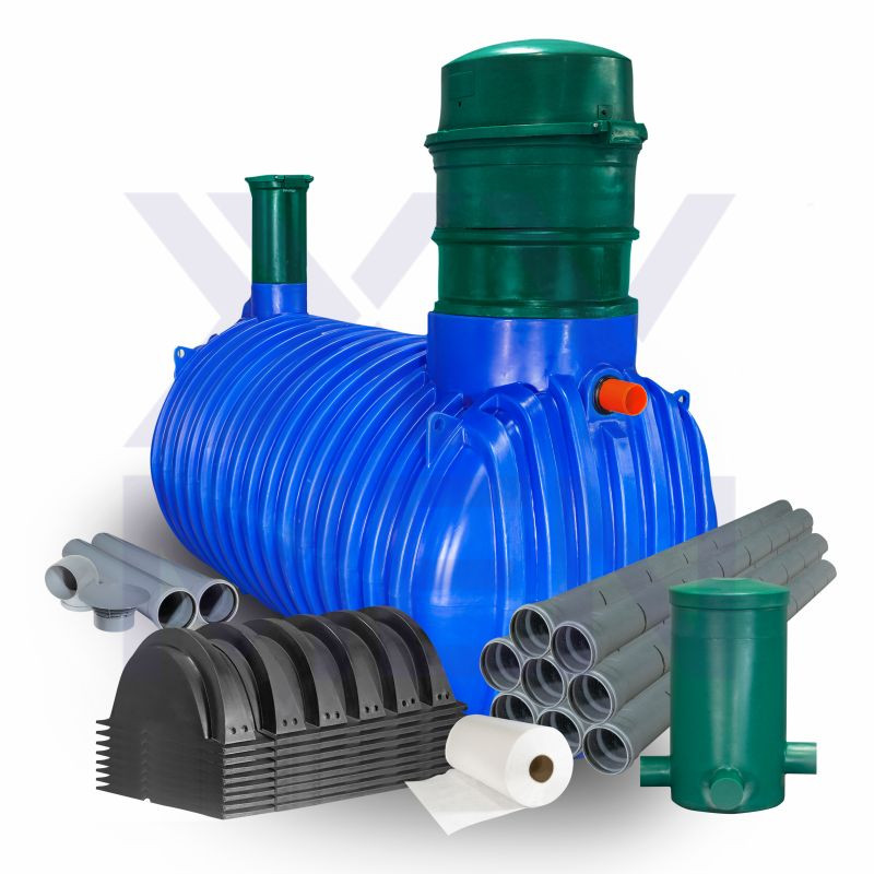
150 L tunnel-drainage treatment plant includes:
– PVC pipe DN 110 grey, 1 m – 3 pcs.
– Distribution manhole DN400 H-0.7 m – 1 pc.
– PVC elbow DN 110 87° grey – 1 pc.
– Infiltration Tunnels 150L – 10 pcs.
– PVC Drainage Pipes DN 110 grey 2m – 5 pcs.
– Ventilation chimney – 1 pc.
– Geotextile, 2m width – 11 linear meters
A treatment plant with 300L tunnel infiltration includes:
– PVC pipe DN 110 grey, 1 m – 3 pcs.
– Distribution manhole DN400 H-0.7 m – 1 pc.
– PVC elbow DN 110 87° grey – 1 pc.
– Infiltration Tunnels 300L – 8 pcs.
– Ventilation chimney – 1 pc.
– Geotextile, 2m width – 11 linear meters
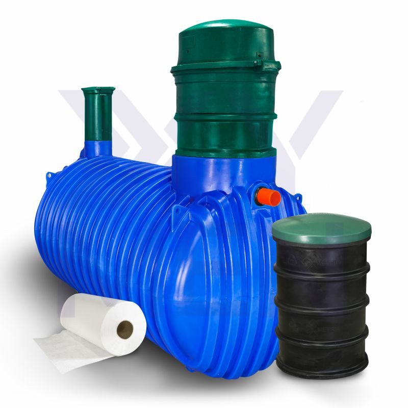
A treatment plant with an infiltration well includes:
– Infiltration well DN 600 H-1m perforated with side drainage holes
– DN 600 green lid
– Geotextile 2m x 2m
Tank extensions are available:
– DN 200, 50 cm and 100 cm height
– DN 600, 50 cm and 100 cm height
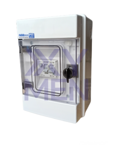
For safe operation of the device, you should install a fuse box.
The tank has a CE ITB Certificate, a concise installation manual, and guidelines for assembly and operation.
Installation available nationwide by professional installation teams—to be arranged individually.
Have questions? Call us, and we’ll help you choose the best solution for you.
